Design a microfluidic chip with Quake valves
A Quake valve is a two-layer PDMS microvalve where a rounded control channel crosses over a rectangular flow channel; pressurizing the control line pinches the flow channel shut. Glyph's Microfluidics component library now ships a dedicated Quake valve (crossing) part (mf.quakeValve, in ) that draws both layers from one set of parameters — reach for it directly if a stock two-layer crossing is all you need. This guide instead builds the crossing manually from two Straight-channel parts on separate GDS layers, which is still the right approach for a custom footprint (an asymmetric seat, a non-square valve, or a hand-placed ganged array) that the parametric part doesn't cover, and it's a clearer way to see how the two-layer crossing actually works underneath.
- Time: ~15 min
- You'll need: a modern desktop browser and nothing else — Glyph runs entirely client-side and your files never leave your computer.
 View full image
- Open the editor. Go to Glyph — a blank document loads with one default layer.
- Add two layers for the two Quake masks. In the Layers panel, click + twice to add layers named "Flow" and "Control" (click each layer's colour chip to rename and recolour it). Real Quake devices are two separately molded PDMS layers bonded together, so keeping flow and control on two distinct GDS layer numbers is what lets a mask writer, DRC, or any downstream tool tell them apart.
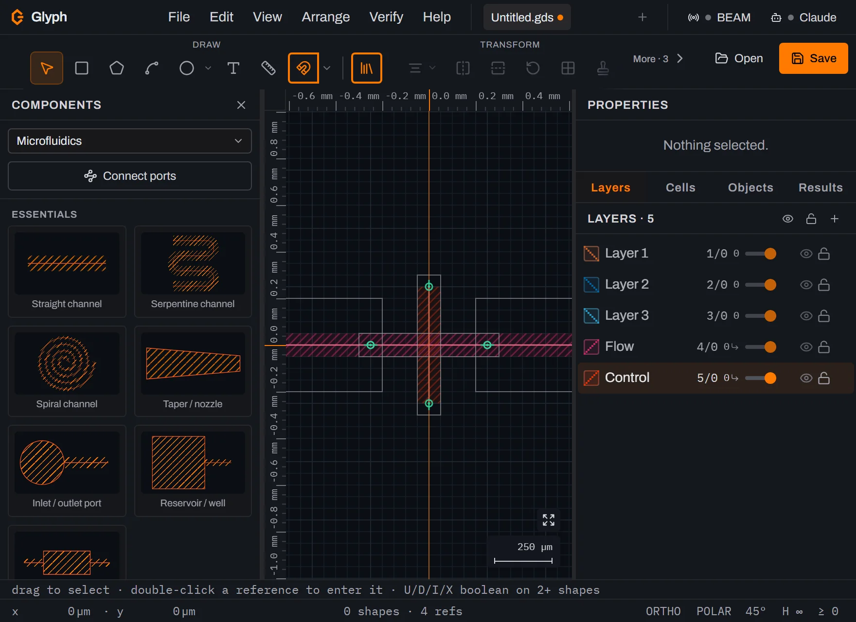
- Make "Flow" the active layer, then place the flow channel. Open , choose Microfluidics from the dropdown, click the Straight channel card, set Length and Width in the Properties panel (500 µm / 100 µm is a reasonable start), then click the canvas at the origin to drop it. If the canvas turns into one solid colour with no visible edges right after you drop it, that's expected, not broken — a 500 µm channel is bigger than the default zoom-to-fit view, so it fills the whole screen; press
Ctrl+0for to see the actual shape. - Add inlet and outlet ports. Still in Microfluidics, click the Inlet / outlet port card and drop it right at the channel's left end. Because that click lands on an open channel end, Glyph's port snapping recognizes it as a docking target and auto-orients the port for you — no
Rneeded — so the port's own connecting stub mates straight onto the channel and the pad sits clear beyond the join, not overlapping it. Click the card again and drop the second one at the channel's right end the same way; it self-orients too, facing the opposite direction so its pad clears the crossing on that side instead. (This auto-orient only fires when you drop near an existing open port — a click further away just places the part at whatever rotation the ghost was already showing.) - Make "Control" the active layer, then place the control channel. Click Straight channel again, press
Rwhile the ghost is armed to rotate it 90°, and drop it so it crosses the flow channel. Select each channel and typeX 0/Y 0into the Properties panel if you want the crossing dead-centre. - Zoom in on the crossing. You should see two channels — one per layer, in two colours — overlapping at a right angle. That overlap footprint is the valve: fabrication molds the control channel with a rounded cross-section (a reflowed-photoresist master) so pressurizing it deflects a thin membrane down and pinches the flow channel shut beneath it. Glyph draws the two mask layouts; the membrane deflection itself happens in the cured PDMS, not in the file.
- Repeat the crossing to gang more valves. Copy the control channel (
Ctrl+C/Ctrl+V) and reposition each copy over a new point on the flow line, or branch the flow line with a T-junction or Cross junction card. Every additional valve is just another Control-layer channel crossing a Flow-layer channel — this is how a control line drives many valves off one pressure source. - Check channel spacing with DRC. , set a min-spacing rule on the Flow layer that matches your process, then press
F7. This catches flow-channel segments that drifted too close together anywhere outside the intended valve crossings. - Export both masks.
Ctrl+S, save as.gds. Layer numbers carry straight through the file, so a mold-maker or your own script can pull the Flow-layer polygons for one mold and the Control-layer polygons for the other.
What you built
A two-layer Quake valve crossing: a Flow-layer channel with inlet/outlet ports, crossed at 90° by a Control-layer channel, both dropped from Microfluidics library parts and checked with a spacing DRC. Every part you placed is a small cell plus one instance — the same SREF mechanism a hand-drawn repeated feature would use — so it moves, copies, and exports like anything else. Repeating that one crossing across a branching control line is exactly how real Quake chips build a valve array (microfluidic large-scale integration, in Thorsen/Quake's original sense) out of one recurring building block.
Next steps
A valid two-layer mask design is only the layout half of a Quake device — building it still means casting PDMS off two separate molds and bonding the flow and control layers together. See maskless lithography for how a design like this one turns into an exposed mold master without a physical photomask, or the photoresist glossary if any term above was new.