Lay out a MEMS comb-drive actuator
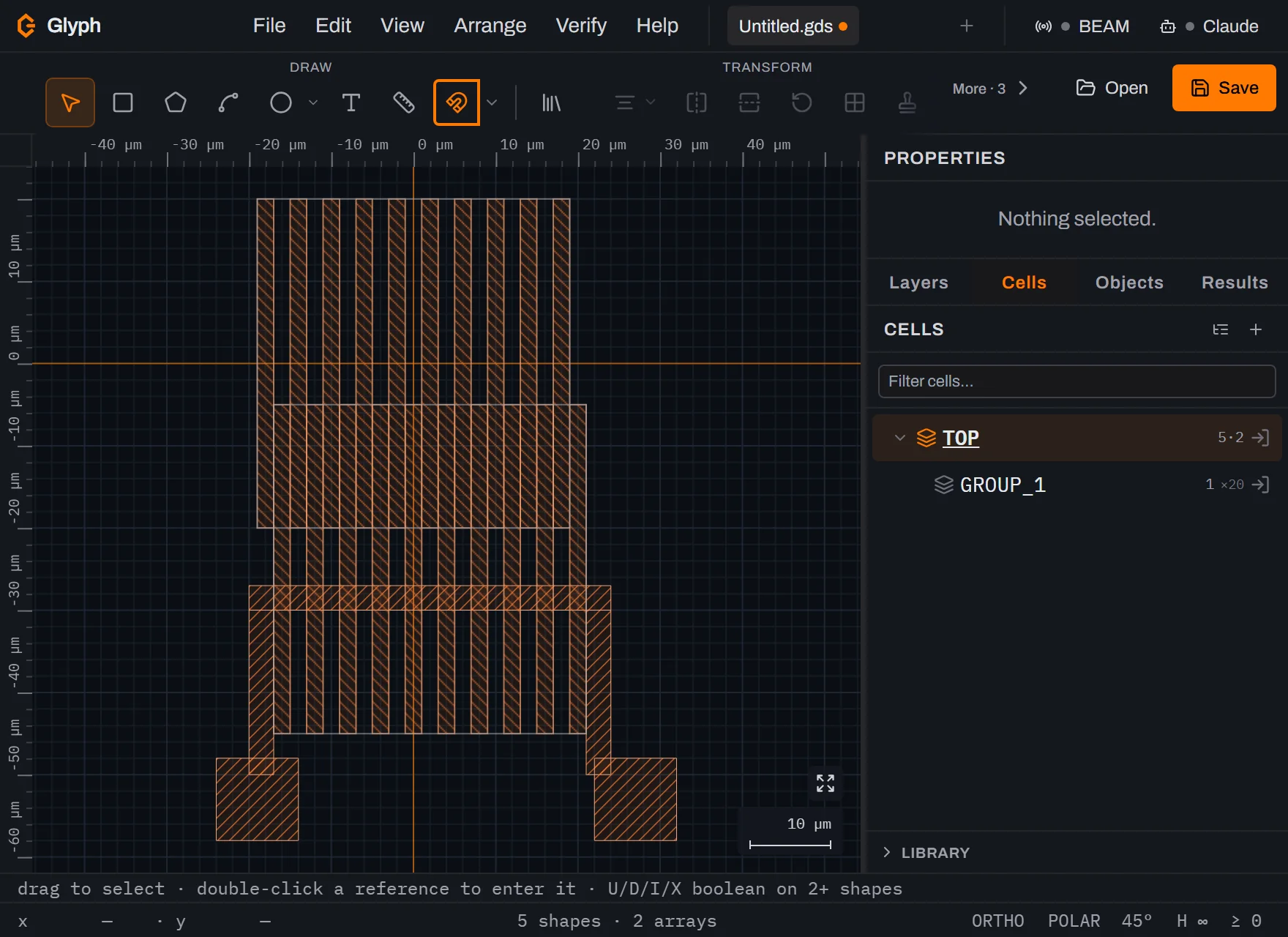
A MEMS comb-drive actuator pairs two interdigitated finger combs — a fixed stator and a suspended rotor — on cantilever flexures. Glyph's MEMS component library now ships a ready-made, parametric comb drive (Component library → MEMS → Actuators → Comb-drive actuator) if you just need the part — but this guide builds one from primitives on purpose: a single finger repeated with AREF, then flattened and boolean-unioned into the released structure. The same moves — array, flatten, union — are how you lay out any MEMS geometry the libraries don't cover, and by the end the parametric component's own construction will be legible to you.
- Time: ~25 min
- You'll need: a modern desktop browser and nothing else — Glyph runs entirely client-side and your files never leave your computer.
 View full image
- Open the editor. Go to Glyph — a blank document loads with one default layer. Most MEMS devices etch through a single structural layer, so this one layer is enough for the whole device.
- Draw one comb finger. Press
B, drag a thin rectangle, then type exact W / H into the Properties panel — e.g. 2 µm wide by 40 µm long. This single finger becomes the template for the whole comb. - Group it into a cell. Right-click the finger → Group. It's replaced by one instance of a new cell — delete that lone instance; you'll place the real array next.
- Array the finger into a stator comb. In the Cells panel, click the finger cell's Insert Array icon, set rows
1/ cols to your finger count (e.g.20), and a column step equal to your finger pitch (finger width + gap, converted to nm), then click the canvas to place the whole bank as one AREF — a rows×cols grid of the same instance, not twenty separate rectangles. - Array a second, offset comb for the rotor. Repeat step 4 with the same finger cell, but place the new AREF shifted by half a pitch in x and by your intended actuation gap in y, so its fingers interleave into the stator's gaps without touching.
- Draw the shuttle, suspension, and anchors. With
B, draw a bar across the rotor comb's fingers to tie them together (the shuttle), two thin cantilever beams running from the shuttle to two anchor pads, and the anchor pads themselves — same layer, plain rectangles. - Flatten the arrays. inlines both finger AREFs into ordinary polygons — boolean operations need real shapes, not references.
- Fuse the rotor into one polygon. Select the rotor's flattened fingers, shuttle, cantilever beams, and anchor pads, then press
U(Union) — the whole suspended structure becomes one continuous polygon, the way it will actually etch and release as a single part. Repeat for the stator fingers plus the stator's anchor. - Check the finger gap with DRC. , set a min-spacing rule on the structural layer matching your process's smallest resolvable gap, then press
F7— that gap sets both your drive's capacitance and whether the etch can resolve it at all. - Export.
Ctrl+S, save as.gds.
What you built
A two-comb MEMS electrostatic actuator: a fixed stator comb and a suspended rotor comb, each drawn once as a finger cell and repeated with an AREF instance array, then flattened and boolean-unioned into two continuous, released polygons connected by a cantilever suspension — checked against your process's minimum resolvable gap. The AREF step is the one that scales: twenty fingers placed as one instanced array keeps the document light and keeps every finger identical if you widen the pitch later. The union step reuses an ordinary Boolean operation for a MEMS-specific purpose — collapsing overlapping rectangles into the single continuous shape that will actually etch and release as one part.
Next steps
A checked comb-drive layout is a mask design, not a released device — turning it into a working actuator still means exposing a resist on the structural layer, etching, and releasing the suspended parts. See maskless lithography for how a design like this one gets exposed without a physical photomask, or the photoresist glossary if any term above was new.