Editing
| Shortcut | Action |
|---|---|
Ctrl + A |
Select all in the active cell |
Ctrl + I |
Invert selection |
Ctrl + C / Ctrl + X / Ctrl + V |
Copy / Cut / Paste |
Ctrl + Shift + V |
Paste in place (original coords) |
Ctrl + D |
Duplicate (see Move, Arrange) |
Ctrl + Z / Ctrl + Shift + Z |
Undo / Redo |
Delete / Backspace |
Delete selection |
Arrow keys |
Nudge selection by one grid step |
Shift + Arrow |
Nudge by 10× grid step |
Escape |
Cancel draft / clear selection |
? |
Toggle keyboard cheat sheet |
The Edit menu, the command palette and the toolbar's Undo/Redo tooltips name what they act on — e.g. "Undo Draw shape" or "Redo Boolean" — instead of a bare "Undo"/"Redo", falling back to the bare verb (with its usual disabled reason) when there is nothing to undo or redo.
 View full image
Right-click on the canvas for a context menu (cut, copy, paste, boolean ops, group, move to layer).
Shift+click and Ctrl+click (Cmd+click on macOS) both toggle a single shape or reference into or out of the selection. Click one that's already selected to drop just that one — the drag that would normally follow a click never starts on it, so a Ctrl+click to deselect can't accidentally drag the thing you just removed. Click one that isn't selected and either modifier adds it without disturbing the rest. Ctrl+click is the idiom KLayout and most other CAD tools use for this; Shift+click did it first here and both now behave identically. A Shift-held drag still additively marquees; a plain drag on empty space starts a fresh marquee and replaces the selection.
Very large objects are picked by their edge, not their fill. If an object is bigger than the whole viewport — an outer frame, a whole-chip instance placed in the top cell — clicking inside it does nothing, so a marquee can still start there instead of dragging the giant thing around. Click its visible outline to select it, or zoom out until it fits. If none of its edges are on screen, pick it from the Objects panel or Ctrl + A. Objects small enough to see in full are unchanged: click anywhere on them.
Fence select picks everything a line you draw crosses — the fastest way to grab an irregular cluster (a diagonal row of pads, a routed chain) that no rectangle fits. Run , or find it in the command palette (Ctrl + K, type "fence"); it has no default key, but you can bind one in Keyboard shortcuts. The status bar then says what to do: click points on the canvas to lay down a line (each click adds a point; nothing snaps), then press Enter or double-click to select. To place the points from the keyboard instead, press Enter before the first one: the typing box opens by the cursor, and each x,y (absolute) or @dx,dy (from the last point) followed by Enter adds a point, the same syntax the Polygon tool takes — then Enter on an empty field selects. A fence needs at least two points: finishing with one (including a double-click as your first action) keeps the fence going and says to click one more — or to type or click one more, when you finished from the typing box. After a clicked point the same box is one Tab away. Backspace removes the last point; Esc, a right-click, switching tools, or switching tab or document cancels and leaves the selection alone ( visits your other tabs and comes back, and keeps the fence). The line selects every shape and reference whose outline it crosses or touches — a polygon's edges, a path's widened edges (a zero-width path's centreline), a text label's or bitmap's box, an instance's grey frame. A line drawn wholly inside a shape does not select it, the same rule as picking a very large object by its edge, so fencing through a dense area never also grabs the big fill underneath. Hidden and locked layers are skipped. Construction guides are selected only when the line crosses no real geometry. Hold Shift on the first click to add to the current selection, or Ctrl (Cmd on macOS) to toggle what the line crosses in or out; otherwise the fence replaces the selection. Like a marquee, a fence is a view act: no undo entry, no unsaved-changes dot. A fence that crosses nothing says so, and clears the selection unless you held Shift or Ctrl.
Window select and Crossing select (both under , and in the command palette) use the same clicks to draw a closed polygon instead of a line — the tool for an L-shaped or diagonal region no rectangle fits. Click its corners (or type them, as for the fence), then Enter or double-click; the polygon closes itself (it needs at least three corners; finishing with fewer keeps it going and says how many more to click — or to type or click, when you are typing them). Window selects every shape and reference whose whole outline lies inside the polygon; Crossing also selects everything whose outline the polygon's edge crosses or touches. The outline is the same one the fence uses — a path counts with its full width, a text label by its box, an instance by its grey frame — so a polygon drawn wholly inside a big fill selects it under neither mode. Where the polygon's edges cross each other, any region the outline loops around counts as inside. Shift / Ctrl on the first corner, Backspace, Esc and the no-undo-entry rule all work as for the fence.
(Ctrl + I) swaps the selection within the active cell to everything else that's selectable there — hidden and locked layers stay excluded either way, and with nothing selected it's the same as Select all. extends the selection to every other object matching an already-selected one: for a shape, the same layer/datatype and kind (a boundary never pulls in a path sharing its layer, and 1/0 never pulls in 1/4); for an SREF/AREF, the same target cell. It's disabled with nothing selected. Both are view acts like Select all — no undo entry, no unsaved-changes dot.
(KLayout's Edit → Selection → Change Layer) sends every selected shape onto whatever (layer, datatype) pair is currently active — the same pair a freshly drawn shape would land on — as one undo entry, no matter how many different layers the selection started on. It refuses, with a toast, when there's nothing selected, when every selected shape is already on the active pair, when the active layer is locked or hidden (it says which), or when the selection is references only (an SREF/AREF has no layer of its own — enter the cell first). A shape sitting on a locked source layer is skipped rather than blocking the rest of the move, and the toast names how many were skipped that way.
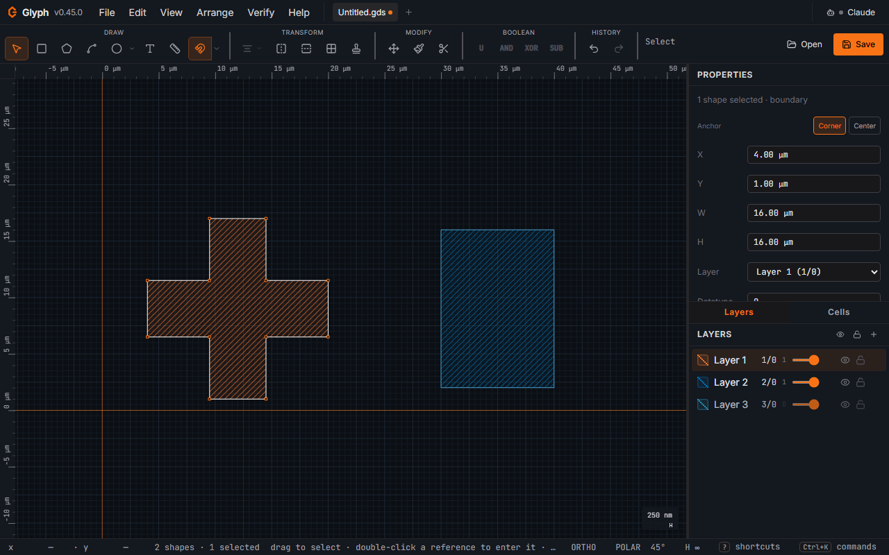
Properties panel is authoritative: typing a number and pressing Enter (or blurring the field) overrides drag-edited values. Escape inside a field reverts. Click (or Tab) into a numeric field and it selects the whole value, so typing immediately replaces it — no need to select-all first. Number fields in dialogs select the same way, including the field a dialog opens on: the first click into a number field you have not typed in yet selects its value, and a second click places the cursor. Enter in a number or text field of a dialog that has a primary button applies the value and runs the dialog; a multi-line box (Send feedback's message) keeps Enter as a new line. An emptied number field is refused where you typed it — it outlines red and reads "Enter a value" — rather than read as 0; leaving it empty puts the previous value back. A number field here reads a plain decimal only — 1.5, -3, or with an exponent 1e3 — so a hexadecimal-looking 0x10 is not read as 16. A length field (X, Y, W, H, Line width…) also takes a unit after the number, the way it shows its value: 100 µm, 100um, 0.1 mm or 250 nm; a bare number is in the display unit. Enter on a draft it cannot read — abc, or 100 m — is refused where you typed it: the field outlines red and the reason shows under it (a field at the bottom of a scrolling panel scrolls it into view). Leaving the field puts the previous value back. A dialog's length fields read a unit the same way — Go to coordinate's X and Y, Chamfer / Fillet's distance, the Text dialog's Size, Fill's region, pitch, halo and tile size, Close open contours' Endpoint tolerance, the Wafer layout's sizes, Mark set's positions (100 µm, 0.1 mm) and Bitmap import's Scale (100 nm or 0.1 µm/px); a bare number is in the unit the field names, and a draft it cannot read outlines the field red and says why, beside the field or the dialog's button. Array's Rows and Cols, Polar array's Copies, the Design rules limits, Fill's Target density and Close open contours' Minimum area read a plain number only, with no unit after it (the Design rules columns name their unit), and refuse any other draft: nothing runs until it is fixed. The panel lists the selected object's own type-specific fields first (a text label's Size, a path's Line width (distinct from the bbox W field below it; the chip beside a selected path on the canvas reads Line for the same value, since W always means the bounding box), an AREF's rows/cols/steps…), with position and size (X, Y, W, H), then the Transform tools (Move by Δx/Δy, Rotate, Scale, Offset), then Layer/Datatype and the read-only measurements below — the most-used field for whatever you selected is always nearest the top, and with one box or polygon selected on a 1280×800 window Move's Δx is on screen without scrolling. When the panel's content is taller than the pane it scrolls, and a scrollbar plus a faint bottom-edge fade both show there's more below. The W and H fields are editable for any shape selection — typing a new width or height non-uniformly rescales the selection (the other axis is held fixed) about whichever point the Anchor toggle currently lights (c126, C126-T1tb: before this fix W/H always pivoted on the bounding-box centre regardless of the lit chip, so a Corner-anchored X moved on its own the moment W or H changed, with nothing explaining why). Editing W/H on a bitmap, SREF, or AREF falls back to a uniform scale since those carry a single magnification factor. The Layer dropdown sends the selection to a layer (and its declared datatype/purpose), and the Datatype field sets the GDS datatype on the selection directly — use it for dose classes or pin/label variants that share a layer number (e.g. 1/0 drawn vs 1/10 pin). For a selection of filled shapes the panel shows the true (shoelace) area and perimeter — summed across the selection, so concave combs / rings / van-der-Pauw crosses are measured correctly rather than over-stated by their bounding box; for paths it shows the centerline length. All values follow the active display unit. The Anchor toggle above X/Y switches X/Y and W/H alike between the selection's bounding-box Corner (default — the corner X/Y already reads stays fixed as W/H change) and its Center (the centre stays fixed instead) — pick Center to place a mark specified by its centre (e.g. an alignment cross at x = +45 mm) by typing the spec value directly instead of subtracting half its width.
Fluidic resistance (Microfluidics). Selecting a single width > 0 path — including a placed Microfluidics-library instance like Straight/Serpentine channel or Flow resistor, whose channel is exactly one such path — shows a read-only Fluidic resistance readout below the area/length block: Poiseuille resistance for a rectangular cross-section, computed from the channel's own width and length plus a Height and Viscosity you enter (defaults 50 µm and 1.0 mPa·s = water). Both are remembered across sessions as app-wide settings, not saved per-shape or per-document, since GDS geometry has no height and carries no fluid. This is a per-channel estimate only — network effects, junctions, and compliance between channels are not modelled; use a dedicated flow-control tool (e.g. Elveflow ESI, Fluigent OxyGEN) for that.
Selection area (sum). Alongside the per-item Area/Perimeter/Length block, any selection of one or more objects shows a read-only Selection area (sum) total: the sum of every filled boundary/box's true area plus every width > 0 path stroked into its ribbon polygon (the exact same math the CIF writer uses to widen a path), with a selected SREF or AREF expanded one level — its target cell's own shapes counted at their real size (magnification² × instance count for an array). Text, zero-width paths, bitmaps and construction shapes never count toward it, and the row says so ("3 text / 1 zero-width path not counted") rather than silently under-reporting; a ref found one level inside an already-expanded ref is reported as a "deeper instance" rather than expanded again. Overlapping shapes are summed, not unioned — two shapes covering the same ground count twice here, unlike the true (non-overlapping) manufacturable area a layer-operations union would report — which is why the label says "sum". Hover the value for the exact nm² figure; an extremely large selection shows "…" briefly while the total waits for the browser to be idle, and one large enough to exceed the same per-shape ceiling a whole-layer boolean refuses at reports that refusal instead of a number. It is printed in your display unit (Settings → Units), the same unit as the per-item Area row, so the two never disagree on units. A self-crossing boundary (a bowtie, a pentagram) counts the ground it actually covers, not the signed shoelace total that would cancel its lobes against each other.
Vertex and edge editing
With a single shape selected:
- Drag a vertex handle to move that vertex (or, on a rectangle, to resize — vertex drag on an axis-aligned rectangle keeps it rectangular).
- Drag a straight edge of a rectangle to push/pull that edge. The two vertices on the edge slide together while staying snapped to the grid.
- Alt-click an edge to insert a new vertex at that position.
- Alt-click a vertex to delete it (minimum 4 for boundaries, 2 for paths).
Construction geometry (SolidWorks-style)
Any shape can be marked For construction in the Properties panel. Construction shapes render with a dotted outline and no fill, participate in snap and measure, and are excluded from .gds export — they are pure visual/alignment guides.